FIG. 2
TEN INCH SOFTENERS
As shipped from the factory, each control is equipped as a 8-
inch unit. A 10-inch eductor and flow control is included with
each unit for conversion for use with 10-inch softener tanks.
NOTICE: To prevent injury, convert units to ten inch
configuration prior to installation.
For the eductor, refer to Fig. 2.
• Remove the three screws on the eductor cap and remove
cap.
• Remove the eductor screen.
• Pull out the blue nozzle and replace with the light brown.
• Reverse the procedure for reassembly. To prevent leaks,
make sure the gasket is in proper position.
For the backwash flow control.
• Remove the u-clip of the drain elbow assembly and pull the
drain elbow straight off.
• Remove the back wash flow control located behind the
elbow. Put the #2 restrictor in it's place.
• Reverse the procedure to reassemble.
PLUMBING CONNECTIONS
Two methods of connecting the water softener to the plumb-
ing system are available. Shipped with each softener is a
Culligan
®
Cul-Flo-Valv
®
bypass valve, either PN 01-0124-88
or PN 01-0102-38. If local conditions warrant, you may use the
sweat adaptor kits, PN 00-3314-44 or PN 00-3314-45.
NOTICE: The Soft-Minder
®
meter cannot be used with the
sweat adaptors.
CAUTION: Close the inlet supply line and relieve
system pressure before cutting into the plumbing!
Flooding could result!
CAUTION: When making sweat connections,
remove all plastic and rubber components which
contact brass or copper. Damage to these
components may result when not removed.
6 / CULLIGAN ESTATE
®
2/2M WATER CONDITIONER
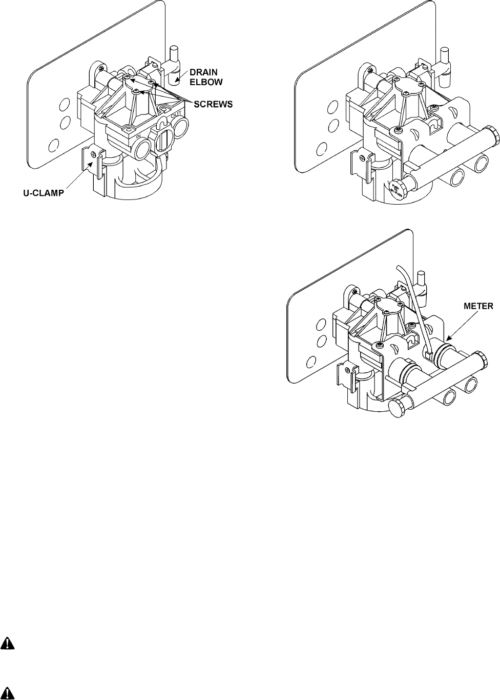
FIG. 3
BYPASS VALVE INSTALLATION - TIME CLOCK
UNITS ONLY
The bypass valve connects directly to the backplate of the
valve with a pair of screws (Fig. 3). To facilitate this connec-
tion, remove the plate by pulling up on the u-clip on the back
of the valve. Lubricate all o-rings with silicon lubricant.
BYPASS VALVE INSTALLATION - SOFT-MINDER
METER ONLY
The Soft-Minder meter is placed between the bypass valve
and the control (Fig. 4). Make sure the meter is on the outlet
port of the control. A pair of elongated bolts are packaged
with the meter to hold the bypass valve to the back plate of
the control. Lubricate all o-rings with silicon lubricant.
SWEAT ADAPTOR INSTALLATION
The sweat adaptors use a snap ring to hold them to the
backplate of the control valve. The back plate will need to be
removed from the valve for this connection. A pair of snap
ring pliers, PN 00-5916-09, are needed for this connection.
FIG. 4
 Manymanuals.com
 Manymanuals.de
 Manymanuals.fr
 Manymanuals.it
 Manymanuals.pl
 Manymanuals.cz
 Manymanuals.es
 Manymanuals-pt.com
Comments to this Manuals